FBG (Fiber Bragg Grating) Array

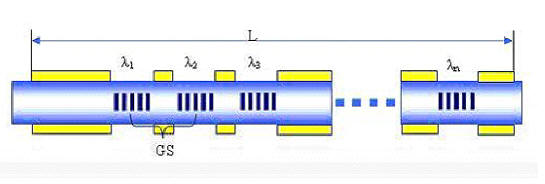
Alxenses’s Fiber Bragg Grating (FBG) array is produced using advanced fabrication technique to write many FBGs in a single strand of optical fiber without any splicing points. The mechanical strength of Alxenses’s FBG arrays is therefore significantly better than FBG arrays produced by slicing many FBG arrays produced by slicing many FBGs together. The high quality FBG array with customized wavelength and spacing allow distributed measurement over long distance. FBG arrays are particular suitable for large-scale sensing in strain, temperature or pressure monitoring in oil, gas, civil engineering, aviation and marine industries.


Features:

  • Low insertion loss
  • Spliceless FBG Array
  • Customized FBG array configuration
  • Accurate FBG wavelength and reflectivity

Applications:

  • Large-scale strain and temperature monitoring in oil, gas, civil engineering, aviation and marine industries.

FBG Array Specifications

    FBG Arrays ( Fiber Bragg Grating Array)
    Parameters Values Units Data Sheet
    Wavelength Range 1510~1590 nm
    Wavelength Tolerance +/-0.5 nm
    FBG length 3 5 10 15 mm
    Reflectivity >70 >75 >90 >90 %
    Bandwidth at 3dB <0.7 <0.7 <0.3 <0.3 nm
    Side Lobe Suppress Ratio (SLSR) >15 dB
    Mini Spacing 10 mm
    Spacing Accuracy <5 mm
    Coating & Recoating Material Acrylate or Polyimide --
    Proof Test >100 kpsi
    Fiber Type SMF-28 compatible / polyimide --
    Fiber Termination Bare Fiber, FC/UPC, FC/APC --
    Pigtail Length from FBG 1m / Customized length m
    Operating Temperature -5 ~ +80 °C
    Storage Temperature -40 ~ +85 °C


FBG Array Enquiry Form

For Customized FBG, please inform us your requirement on the following specification:

FBG Arrays ( Fiber Bragg Grating Array)
Parameters Units Customized Specifications Remarks
Number of FBGs in an Array --   Max. no. is limited to 100 m of fiber with no splicing.
Each FBGs' Wavelength nm

(FBG1) XXXXnm;

(FBG2) XXXXnm;

(FBG3) XXXXnm; ... etc.

Wavelength range: 1510~1590nm.
Please specify in order of locations starting from the input end.

FBGs' position along fiber


mm

1. Distance between each FBG (center-to-center)

2. Pigtail length on each end

*Please provide diagram/drawing if possible

Min. spacing between FBGs
is 10 mm.
The 0-mm position is the input end of the fiber or connector.
Position accuracy is ± 2 mm.
Length of FBG mm    
Reflectivity %    
Bandwidth at 3dB nm    
Side Lobe Suppress Ratio (SLSR) dB   Typ. > 15 dB
Coating and Recoating Material --   Acrylate or Polyimide
Connector Type -- NC: no connector
FP: FC/PC
FA: FC/APC
Example: FP-FA means with FC/PC connector at position 0-mm and FC/APC connector at the other end.

FBG Array Ordering Code

FBG Array - Part Number

AL - (1) ARRAY - (2) nn - (3) FBG - (4) A / P - (5) NC

(1) Product Type (2) Number of FBG in an Array (3) Type of Array (4) Coating Material (5) Connector

ARRAY

nn < 100 FBG: Array of FBG

C: Array of Chirped FBG

A: Acrylate

P: Polyimide

NC: no connector
FP: FC/PC
FA: FC/APC

*Alxenses Company Limited reserves the right to make changes to the FBG Array products without notice.


For FBG and Sensor enquiry, please email to contact@alxenses.com